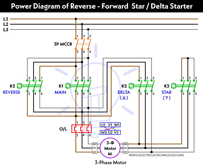


When any start button is pressed supply reaches the A1 point of the contactor and also on the NO point of the contactor which takes continue the contactor in the holding position. When we switch on the supply reaches through overload relay NC point and contactor NC point to start push button. Working of Forward and reverse starter diagram The output of these contactors is fed to the motor through an overload relay for the protection of the motor. Here connect the 3 phase supply to the Over Load Relay same as the input to run the motor in the forward direction but in the case of the reverse contactor, we have to reverse one phase for the reversing of the direction of the motor as shown in the diagram. One of them contactor is a forward contactor and the other is reverse contactor. The output of MCB has to connect with two contactors. In the power diagram of the forward-reverse starter connect the three-phase supply to the input of the MCB.

Then connect two wires from the input and output of the push buttons to the NO point of the contactor for holding of the contactor. Then the output of these NC points connects to the Start push buttons. After that wire has to connect with NC points of the contactor of opposite directions as shown in the diagram e.g for the forward contactor connect to the NC point of reverse contactor and for the reverse contactor connect to the NC point of the forward contactor. The output of the MCB has to connect with the overload relay NC point for reset. Push Buttons – Two push buttons are used here one of them is for the forward direction and the other push-button for the reverse direction.Īs shown in the diagram, we need to connect the power supply in the MCB (Miniature Circuit Breaker). Over Load Relay – Over Load Relays are used to protect the motor against various types of faults like overloading, over-voltage, under-voltage, single phasing, etc.Ĭontactors – Two contactors are used one for the forward direction and the other for the reverse direction. MCB – Two-pole MCB used for Control wiring and 3 pole MCB used for the power wiring. These types of starters are used in various applications e.g- mixing of materials, dying machines, etc. To run the motor of above 05 HP rating circuit has to made in star delta.

These forward and reverse starters are dol type and not used above the 05 HP motors. The figure given below shows the control and power diagram of the forward and reverse starter diagram. As the name defines forward reverse starter is used to run the motor on both sides forward and reverse. In this article, we are going to learn about the forward-reverse starter.


 0 kommentar(er)
